Hello! This month I was focusing more on developing the sensor module prototype that can be easily attached to bins to collect useful waste related data such as bin fullness and bin waste content (via photos of the trash). In this blog I first start off with an update with my Instructables post. Then, I focus more on what I’ve done for the electrical design and the hardware design. It’s a lot, but I hope you enjoy these updates and maybe even learn a couple useful things along the way! As always, let me know your thoughts or if you have any questions. The best way to contact me is on the ZotBins Community Discord.
Instructables Published 📰
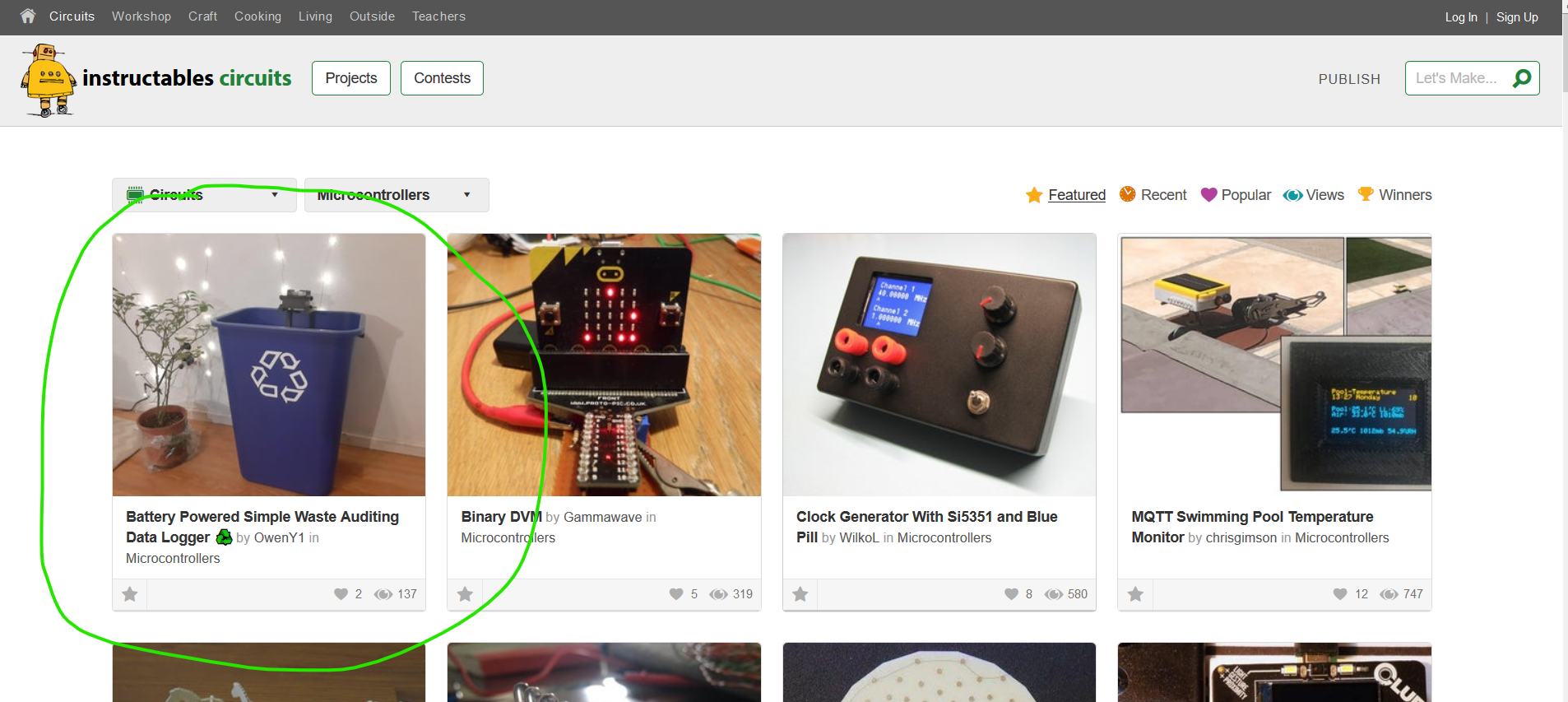
Last month, I was working on creating my Instructables for a simple version of the sensor module. I am pleased to announce that I have finished my draft and it also got featured on Instructables! Special thank you to Sid Lau and others who helped me review it. You can view the Instructables here
I also entered the Instructables into the battery powered contest. I’m hoping to be one of the finalists in the contest. You can help support the project by voting at the bottom of my Instructables page in a Desktop View. Thanks for the support! 😃

Experimenting with Powering the Sensor Module ⚡
Ok, quick background first. I am trying to power the sensor module (which consists of a ESP32-CAM and a HC-SR04) for at least a week, but ideally a month. That way, for maintenance, all users have to do is swap the batteries every once in a while. To make it more sustainable, users could also use rechargeable nickel-metal hydride batteries. To power these components I had to figure out the power consumption levels. So I created the following table with the information I found from Last Minute Engineers (a very fitting title for how I feel sometimes) and Sparkfun. With the table I have, I was able to do some awesome power consumption estimations to figure how many mAh my battery source needed.
Power Consumption
| Description | Current Draw |
|---|---|
| ESP32-CAM Active Mode | 160-260 mA |
| ESP32-CAM Deep Sleep | 10uA |
| HC-SR04 Working Current | 15 mA |
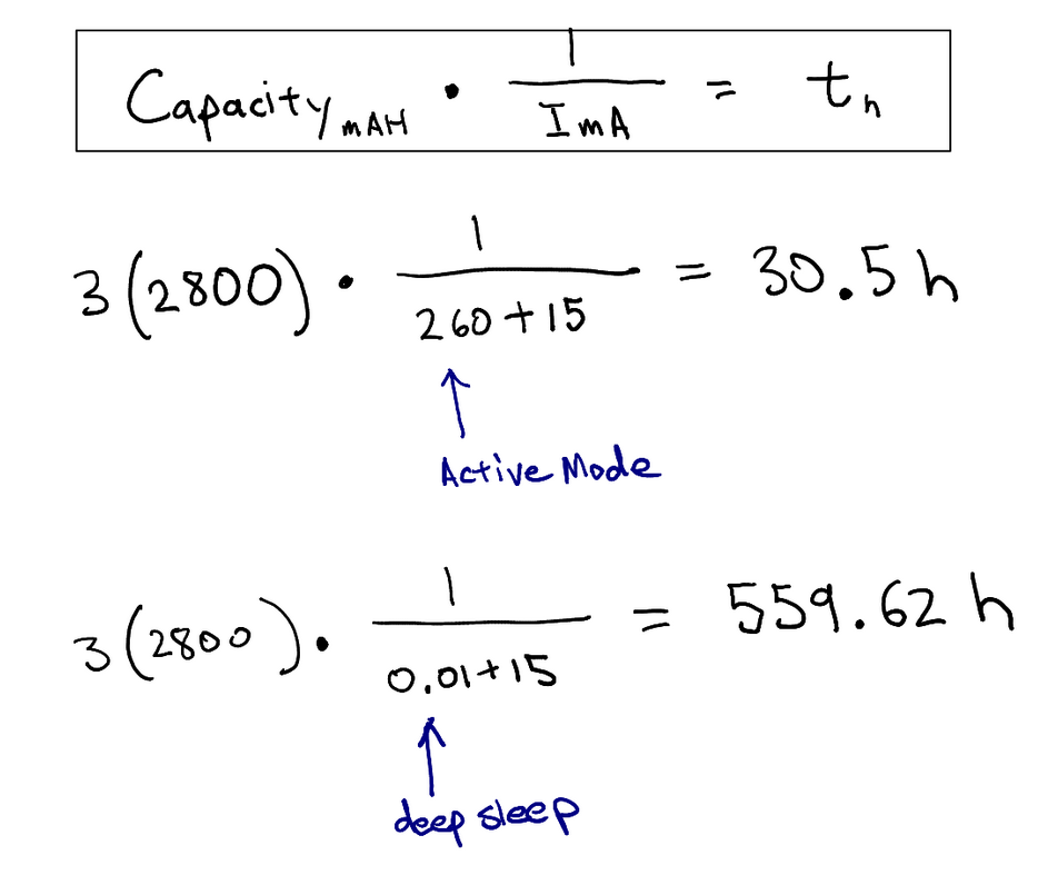
With the table above I settled on using three 2,800 mAh capacity rechargeable AA batteries. I determined this by doing some quick calculations. I first did a high power consumption calculation where the ESP32-CAM is always in active mode, the battery lasted only 30.5 hours. Then I did a low power consumption calculation where the ESP32-CAM was always in deep sleep, the battery lasted 559.62 hours. I know that my code is in deep sleep most of the time so my estimates on how long this will power the sensor module will probably just be a couple hours less than 559.62 hours. So that is more than half a month’s worth of power!
I thought everything was going to work out, but nothing works on the first try. I used 3 AA 1.5 volt batteries in series. That means that the ESP32-CAM along with the HC-SR04 that I use for the sensor module will be powered with 4.5 volts (3 batteries x 1.5 volts = 4.5 volts). Here are a couple problems with that though:
- The sensor module is supposed to operate with a 5 volt power source
- I found that when the total voltage of the power source dipped down to 3.75 volts due to battery depletion, the sensor module was not able to operate.
- It does not use the batteries full capacity
- Because the operating voltage limit was 3.75 volts, as soon as the batteries dropped down in voltage, the sensor module was not able to operate. So the battery wasn’t even completely depleted before the sensor module could not operate
- I was only able to power the sensor module for 19 hours
- That means that every 19 hours someone has to replace the batteries!
Here is a quick graph from Battery Sense that shows the voltage drop as batteries are discharged.
Ok, that sucks. So what’s the solution? I added a boost converter! A boost converter is a circuit that is able to convert one DC voltage to another DC voltage. This means that even if the voltage starts dipping below 3.75 volts, I can still boost the voltage to 5 volts.
Resources:
Structural Design 🔧
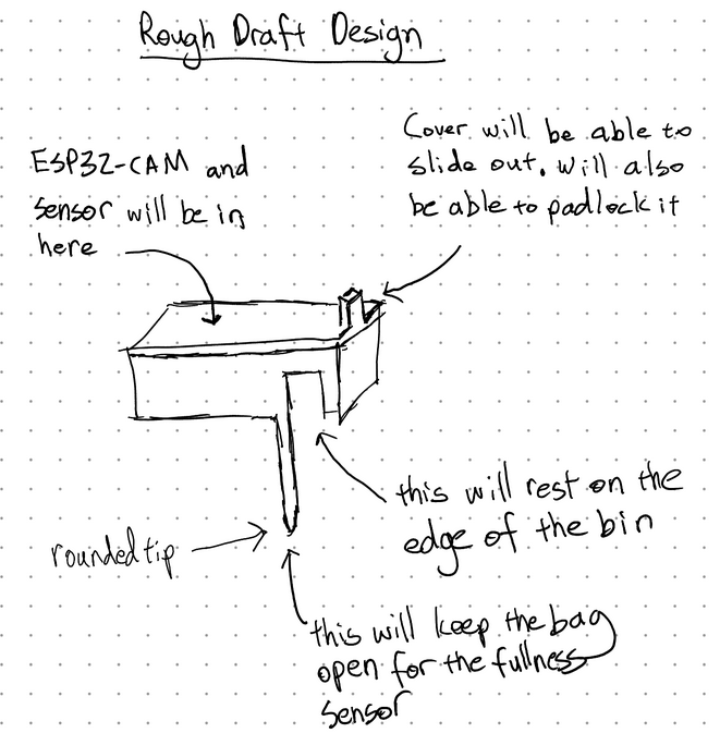
So always I start off with a rough sketch to help me visualize the sensor module enclosure. This was just a start and pretty different from the final design.
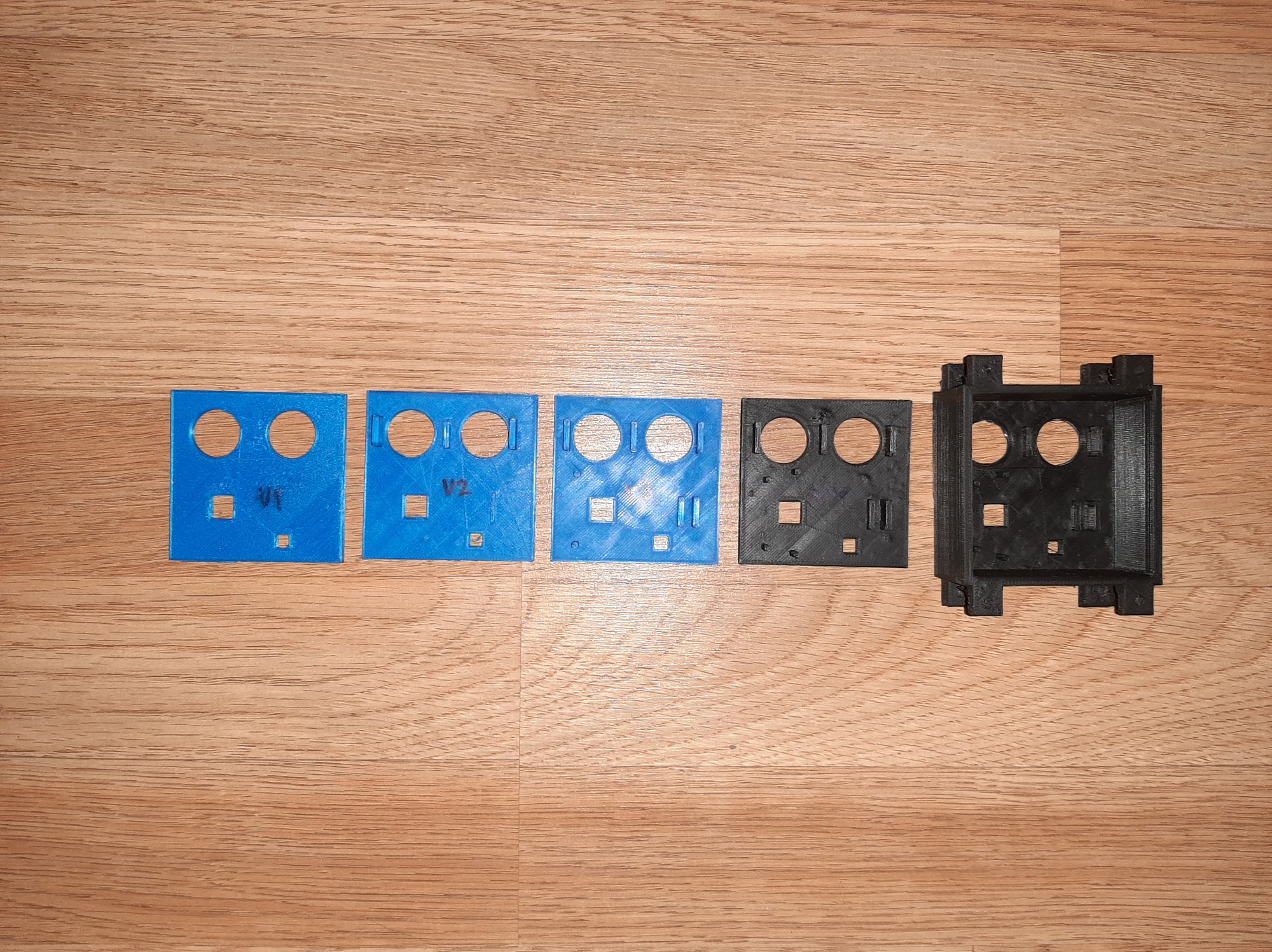
Here are some of the iterations I created for the sensor module enclosure.
Then, after a couple iterations I created and settled on a more complete design. As you can see, it’s pretty different from the sketch above.
Here is 3D-printed prototype.
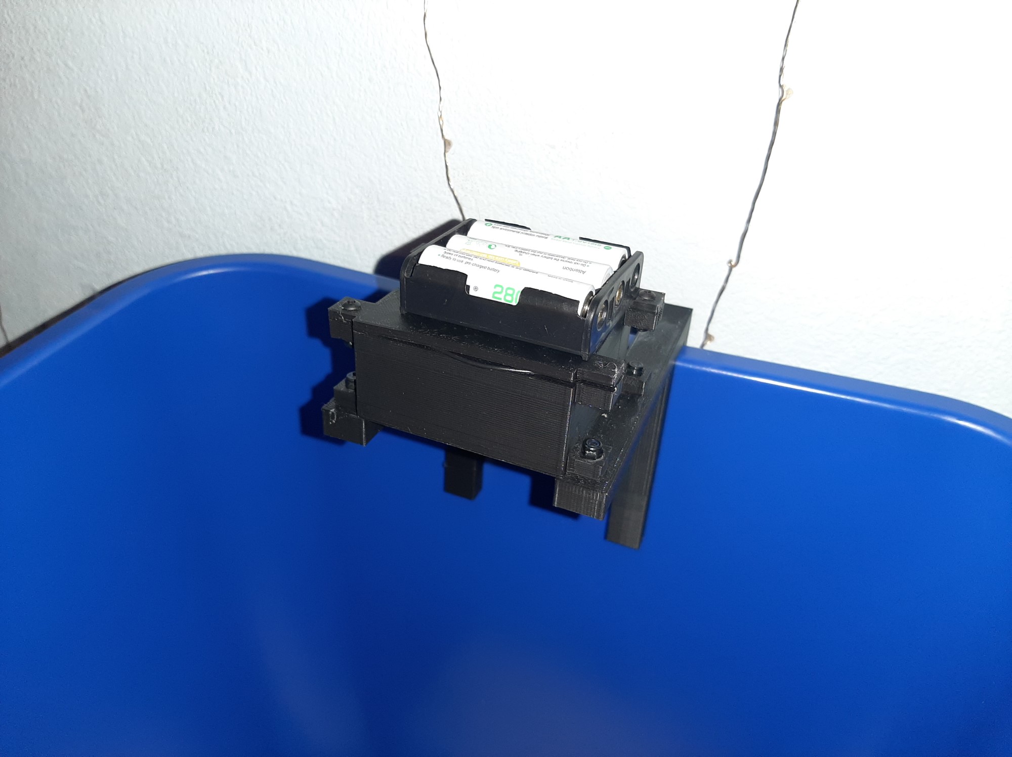
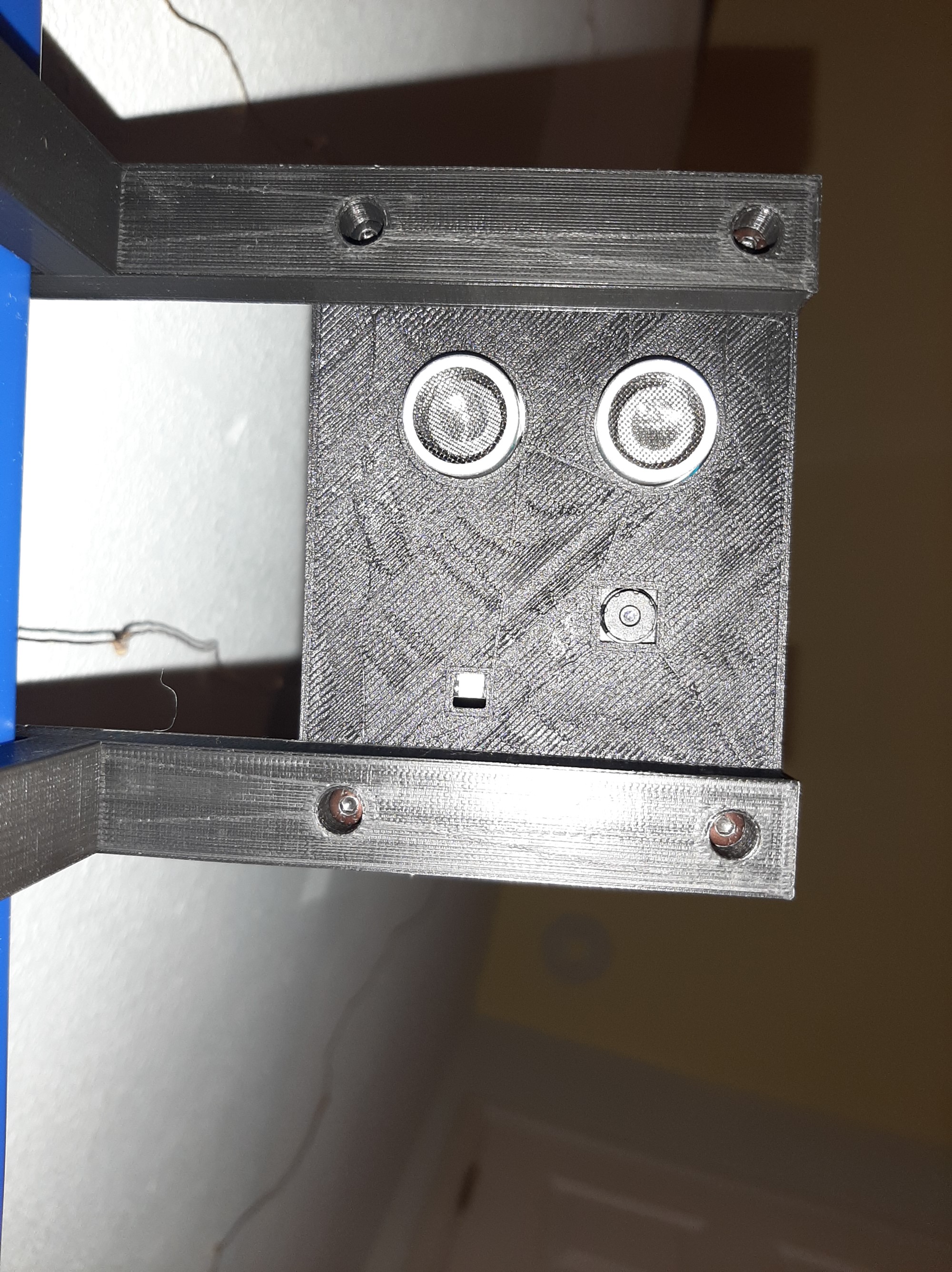
I still haven’t really Fusion 360 mastered it yet, but I think I got a pretty good handle on it. I was able to quickly design a first prototype and 3D printed it. And then I realized it was terrible. And then I designed another and 3D printed it. And then I kept on doing that quite a few times. Even though this sounds like a painstaking process, it might actually be worth it in the long term.
I was watching this a Youtube video from a channel called Design Prototype Test. I learned that when designing things for scalability it is pretty valuable to design your prototypes with rapid prototyping methods as I have. Scaling products and mass producing them is often really expensive and can only be done in large batches for it to be worth it. That means that if you have a design flaw that you just didn’t consider because you never actually had the physical prototype in your hand to test it out, then that entire batch is pretty much wasted and you lose a lot of money. I tell myself all this to cope with the pain of going through the design-build-test process multiple times.
Okay, that’s pretty much it for updates this month. Feel free let me know if you have any thoughts about anything on Discord. Have a great day and keep on being awesome!
– Owen